AllAboutElectronics

Know information about basic electronics,Micro controllers and their programming ,Arduino,Electronic projects and new technology.

hello

Showing posts with label ELECTRONICS. Show all posts

TRANSISTORS

Posted by Unknown in: ELECTRONICS
What is a Transistor?

Transistor is a semiconductor material which is used to regulate current or voltage and is used as switch,amplifier in most of electronic circuits.Transistor stands for Transfer of resistance and has at least three terminals for connection to the external circuit.
Transistor is basically made up of semiconducting materials such as P-type materials and N-type materials.  P-type semiconductor is formed when intrinsic semiconductor is doped with trivalent elements such as Al, Ga and Indium. N-type semiconductor is formed when intrinsic semiconductor is doped with pentavalent impurities such as Phosphorous, Arsenic or Antimony.A transistor is nothing but combination of two coupled diodes.
TYPES OF TRANSISTORS

There are many types of transistors(BJT,FET,UJT etc.,) are available in today's market like and these are based up on the arrangement of P-type and N-type materials ,way of operation .
1.Bipolar Junction Transistor

Bipolar Junction Transistor(BJT) is the most commonly used Transistor.In Bipolar Junction Transistor the conduction is due to two types of charge carriers i.e. both electrons and holes are responsible for current conduction.
Transistor is composed by three parts . They are  1) Emitter 2) Base 3)Collector

Emitter is heavily doped and it is used to emit charge carriers and referred as negative lead.
Base region is very thin and lightly doped .Charge carriers are injected into base and pass on to the collector and is responsible for activating the Transistor.
Collector region is lightly doped and is referred  as positive lead.
There are two basic types of transistors. they are PNP Transistor and NPN Transistor.
PNP and NPN transistors are differed by the current direction.
SymbolNameDescription
npn transistor symbolNPN Bipolar TransistorAllows current flow when high potential at base (middle)
pnp transistor symbolPNP Bipolar TransistorAllows current flow when low potential at base (middle)
The direction of arrow that is shown in the symbol of transistor indicates the direction of current through flowing it. In NPN transistor, current comes out from emitter of the transistor where as in PNP, the current flows into the emitter.
PNP transistor is formed by sandwiching thin layer of N-type semiconductor between two P-type semiconductors.
A PNP transistor is like two PN junction diodes which are placed back to back. At each junction there is a depletion region which leads to potential barrier. Here The Emitter-Base junction is Forward biased and Collector-Base junction is reverse biased . 
As  the Emitter-Base Junction is Forward biased more no of holes will cross the junction and enter into the base region.At the same time very few amount of electrons will flow from the base to emitter.
These electrons will recombine with the equal no of holes and electron -hole pairs are generated. The loss of total no of holes in the emitter is made by the flow of equal no.of electrons from the emitter to the positive terminal of the battery. The flow of holes from Emitter to Base is leads to emitter current and we have IE=IB+IC.

An NPN transistor is formed by sandwiching thin layer of P-type semiconductor between two N-type semiconductors.
 In NPN transistor, current comes out from emitter of the transistor And transistor can be operated in 3 regions .They are 1) Active region 2) Saturation region 3)Cutoff region
In Active region the transistor acts as an Amplifier .In Saturation its acts as closed switch and in cutoff regions it acts as open switch .
Applications of a Transistor

1.Transistor can be used as an amplifier.
2.In digital circuits these Transistor is used as ON/OFF switches.
3.Transistors are used as buffer or impedance matching between mis-matched  electrical circuits.
4.They are used to regulate current,voltage or power.

Also Know about: MICROCONTROLLER

JOGUR JEANS

INDUCTORS

Posted by Unknown in: ELECTRONICS
What is an Inductor?
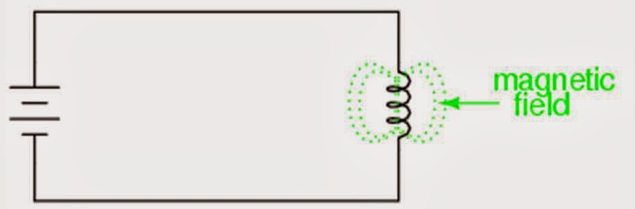
An Inductor is a passive electronic component which stores the energy in the form of a magnetic field. Inductor consists of a coil or  a wired loop. Inductor is used to store amount of current which is flowing in the circuit and later releases the electrical energy to the circuit when the source of power is removed.
inductors
Inductor reduces the current in AC circuits and short circuit in DC circuits.
Symbol of an inductor is given by
                                                      
How Does Inductors work?
When ever current passes through the coil, magnetic flux is generated around it. When the current carrying conductor cuts the magnetic flux , an e.m.f.(electromotive force) is produced. This is known as Faraday's law of electro magnetic induction.
inductors concept
When the current flows through the coil ,The energy is stored in the form of magnetic field and as the current flowing through the inductor changes ,The time varying magnetic field induces a voltage in the conductor ,according to Faraday's law of electro magnetic induction which opposes the change in current.
Inductance
The property of an inductor to oppose the change in current is known as inductance. It is the ratio of voltage to the rate of change of current.
SI Unit of Inductance is Henry(H).
Induced emf is given By
                                    inductors advantages
L      → inductance is Henry
di/dt → rate of change of current
Inductance depends on no.of turns of the coil, permeability of the core material and size of the core.
Lenz's Law
The direction of induced e.m.f. is given by Lenz's law ,which states that the direction of induced e.m.f. is always so as to oppose for the cause for producing it.
Applications of Inductors
about inductors


Inductors are used in various applications of electronics .
1. They are used in analog circuits and signal processing.
2. Inductors are used as energy storage devices in SMPS (Switch Mode Power Supply) to produce DC current.
3. Inductors are used essentially in Transformers .
4. They are used in various types  of filters in communication equipment.

FASTRACK BASICS ANALOG WATCH

Also Know About: DIODES

CAPACITORS

Posted by Unknown in: ELECTRONICS
What is a Capacitor?

A Capacitor is an electrical component used to store the energy in the form of electric fields.  A Capacitor consists of two conductors which are separated by an insulating material called dielectric. 
capacitors principle
Dielectric can be glass,plastic film, paper or any non conducting material. When there is a potential difference between the two plates of the conductor then a static electric field will be produced across the dielectric, causing the positive charge to collect on one plate and negative charge to collect on another plate. The energy is stored in the form of electric field.
The symbol of a capacitor is given by    
                                                                 capacitor symbol
Capacitance

Capacitance is the ratio of the electric charge on each conductor to the potential difference between them. Capacitance is measured in the unit of Farad(F) which is equal to 1 cu per volt.
C=Q/V
C →Capacitance of the capacitor(in Farad)
Q → Electric Charge (in cu)
V → Voltage between capacitor plates (in V)
The capacitance value depends up on the value of dielectric constant.
A capacitor blocks DC and allows AC current to pass through it. When an AC current is given to the capacitor starts charging exponentially and when an load is connected then the capacitor discharges.
Types of capacitors

There are different types of capacitors. Capacitors can be fixed or variable . They are again divided into polarized and non polarized.
Based on the conduction capacitors are divided in to two types. They are
  1)Ceramic capacitors 2)Electrolytic capacitors
Electrolytic capacitor is a fixed capacitor consisting of two electrodes separated by an electrolyte. Electrolytic capacitors provide high capacitance in small volume and are used mostly in Power supply filter circuits at lower frequencies.  Electrolytic capacitors are polarized.
Ceramic capacitors are non polarized and these are purely depend on the dielectric constant of the bulk capacitor. Most of low value capacitors are non polarized. 
Based up on the construction these capacitors are classified in to three types . They are
1) Parallel Plate capacitor 
2) Co-axial capacitor
3) Spherical capacitor
Applications

Capacitors are widely used in various applications of electronics .
1.They are used as the energy storage devices.
2. They are used in filter networks(High pass filter, Low pass filter).
3.They are used in signal processing.
4. Blocking, Coupling and Bypass capacitors are used in amplifiers.

Know About INDUCTORS

DIODES

Posted by Unknown in: ELECTRONICS SEMICONDUCTORS
What is a Diode?
Diode is an electronic component with active electrodes ,which allows the flow of current only in one direction.The two electrodes of the diode are Anode(+) and cathode(-).  Diodes are made up of semiconductor materials like silicon, Germanium.
about diode

The fundamental property of the diode is to allow the flow of current in only one direction.
How PN junction diode is formed?

 about pn junction diode
PN junction diode is made from a combination of 2 extrinsic semiconductors such as P-type semiconductor and N-type semiconductor. P-type semiconductor is formed when intrinsic semiconductor is doped with trivalent elements such as Al, Ga and Indium. N-type semiconductor is formed when intrinsic semiconductor is doped with pentavalent impurities such as Phosphorous, Arsenic or Antimony.
Here the joint between P-type and N-type semiconductors is called as PN junction. At the PN junction electrons from the N-type semiconductor will be attracted to the holes of P-type semiconductor. As a result the electrons and holes at the PN junction will disappear forming a layer called "depletion layer". At the same time P-type semiconductor become more negative and N-type semiconductor will become more positive. This results in a potential difference across PN junction.
This potential difference is called as 'Junction voltage or Barrier Voltage'. This junction voltage will prevents the charge carriers from flowing across the depletion region.
Diode can be used in both Forward Bias and Reverse Bias. The polarity of the applied voltage which allows the flow of current is known as 'Forward Bias'. The polarity of the applied voltage which doesn't allows the flow of current to flow is called as 'Reverse Bias'.
Forward Bias:
pn junction diode
In Forward Bias positive terminal of the Battery is connected to the P-type material and negative terminal of the Battery is connected to the N-type material of the PN junction Diode. In forward Bias the diode acts as short circuit and start conducting , so that current will pass through Diode .But the diode starts conducting After the 'Cut in voltage or Break over voltage'.Cut in voltage is defined as the minimum voltage below which current is negligible above which the diode starts conducting.Cut in voltage for si is 0.7v and Germanium is 0.3v . 
Reverse Bias:
pn junction diode
In Reverse Bias positive terminal of the Battery is connected to the N-type material and negative terminal of the Battery is connected to the p-type material of the PN junction Diode.In reverse Bias the diode acts as open circuit and no current will flow through the diode. 
V-I CHARACTERISTICS OF PN JUNCTION DIODE

pn junction diode working
Diodes are mainly used as Rectifiers, Signal limiters, Voltage Regulators ,Switches ,Signal Modulators , Signal Demodulators,Clippers,Clampers.
TYPES OF DIODES: 

1.LIGHT EMITTING DIODE
2.PHOTO DIODE
  

And also see : TRANSISTORS

RESISTORS

Posted by Unknown in: ELECTRONICS
A Resistor is an Electrical component which limits or regulates the flow of current.The Resistor's ability to reduce the current is known as 'Resistance'. Resistance is measures in ohms(Ω).
Resistance value is stable over a wide range of environmental conditions.

 We can also say that The resistance 'R' of a resistor is equal to the resistivity 'ρ'  times the resistor's length 'l' divided by the resistor's cross sectional area 'A'.
R=\rho \times \frac{l}{A} 
The term Resistor is derived from ohm’s law .Ohm's Law: 
According to ohm’s law Current is directly proportional to voltage.
V∝ I
V=IR , and R=V/I
Here 'R' is the resistance which opposes the flow of current.
Carbon or metal film resistors are the most commonly used resistors.
How to find resistance of a Resistor?
Each Resistor has different type of colors on it .By make use of these colors we can calculate the resistance value of a Resistor.There are 3 types of color codes for a resistor:
1)4 band Resistor
2)5 band Resistor
3)6 band Resistor
Color code for  4 Band Resistor:
In a Four band Resistor 4 Bands make the resistance value.
 Band 1-digit
Band 2-digit
Band 3-multiplier
Band 4- tolerance
The first two bands will take the digit values according to
Black0
Brown1
Red2
Orange3
Yellow4
Green5
Blue6
Violet7
Gray8
White9
You can also remember them as"BB ROY of Great Briton has Very Good Wife".

The 3rd band(multiplier) is color coded as follows:
black – x1        brown – x10       red – x100
orange – x1K   yellow – x10K   green – x100K
blue – x1M      violet – x10M    grey – x100M
white – x1G      gold – .1           silver – .01

The color code for tolerance is as follows:
brown – 1% red – 2% orange – 3%
yellow – 4% green – .5% blue – .25%
violet – .1% gray – .05% gold – 5%
silver – 10%
If the value of resistance is 470 ohm and the 4th band of the resistor was silver(10%) ,then the value range would be resistance value+/- 10% = 460 to 480.


Here in the above example The 4 bands of the resistor are
Brown, Black, Red, Green
(Brown=1),(Black=0),(Red=2)
Tolerance(Green) = ±0.5%
Resistance value=10 x 100 = 1k ohm


Color code for  5 Band Resistor:
In a Five band Resistor 5 Bands make the resistance value.
Band 1-digit
Band 2-digit
Band 3-digit
Band 4-multiplier
Band 5- tolerance


Here the 5 bands of the resistor are
Red,Red,Black,Red,Gold
red=2,Red=2,Black=0,red=100
Tolerance(gold)=5%                                         Resistance value=220X100=22K ohm

Color code for  6 Band Resistor:
In a Six band Resistor 6 Bands make the resistance value.
Band 1-digit
Band 2-digit
Band 3-digit
Band 4-multiplier
Band 5-tolerance
Band 6-temperature coefficient

Here we have 6 bands of resistor are  Yellow,Brown,Red,Orange,Brown,Violet Resistance=412X1000=412k Ohm

Also Know about: Capacitors

MICROCONTROLLER

Posted by Unknown in: ELECTRONICS IC
What is a Micro Controller?

Micro Controller is the most commonly used IC(Integrated Circuit).If a circuit consists of various circuit elements ,then placing thousands of such components in a small chip becomes an IC. We can simply say that " Micro controller is a small computer on a Single IC which contain RAM,Memory and Input/Output peripherals' .

Using of Micro Controller is a prototype or a real time Application. In order to communicate with Micro Controller you need input/output peripherals.
In MC pins are used as peripherals.We can use Microprocessor for the same purpose also. But there are some difference between Microprocessor and Micro Controller .
DIFFERENCES BETWEEN MICRO CONTROLLER AND MICROPROCESSOR

MICROPROCESSOR:


1.Micro Processor can perform no of tasks and run variety of programs simultaneously.
For example, you can listen to music while writing some thing in your writer or doing work in your web browser etc.,
2.These are costly. Efficiency is more as compared to micro controllers.
MICRO CONTROLLER:
1. Micro controller is a computer on a chip optimized to control electronic devices. Micro controller is used to perform single task such as controlling a specific system.
2.Efficiency is more.These are economical and have wide range of uses.

But the reason for using Micro controller is that it is economical and has wide range of uses. We can use Micro Controllers in small projects and application where use of  microprocessor may not require.

Micro Controllers are programmable.You have to program them in order to use them. It has its own programming language and compilers. Program is fed into its memory. When MC is on its works according to the program.
APPLICATIONS


Micro Controllers are used in many electronic projects where artificial intelligence is required. These are used in Robotics . If you want to move your Robot then you can simply program your Micro Controller and you can control your robot.these are used in many applications like ATM machines, cellphones,pen drives,laptops and in many electronic gadgets etc.


BUY MICROCONTROLLERS E BOOK FROM FLIPKART

And also Learn about :TRANSISTORS
Home
Powered by Blogger.

"© Copyright 2014" Allaboutelectronics. · All Rights Reserved. · And Our Sitemap · All Logos & Trademark Belongs To Their Respective Owners·
Template Developed By Blogging Recipes.